> ## Documentation Index
> Fetch the complete documentation index at: https://docs.directenergypartners.com/llms.txt
> Use this file to discover all available pages before exploring further.
# Live Data
Live Data streams real-time measurements from the controller and the devices it interfaces with directly to your
**DCIDE** project's single line diagram. Once enabled, the diagram will visualize power flow and current flow between
components, along with the voltages and statuses reported by each device and port. This provides a live,
at-a-glance view of your microgrid without needing to log in to the controller directly.
This page explains how to enable Live Data on your DCIDE project, how to link the controller to that project, and
how to configure your diagram so that each component displays the correct data.
Before continuing, make sure the controller has been configured and commissioned as described in the
[File Configuration](/configure/index) section, including a valid `devices.json` file with unique `id` values for
each device.
## Enable Live Data on Your DCIDE Project
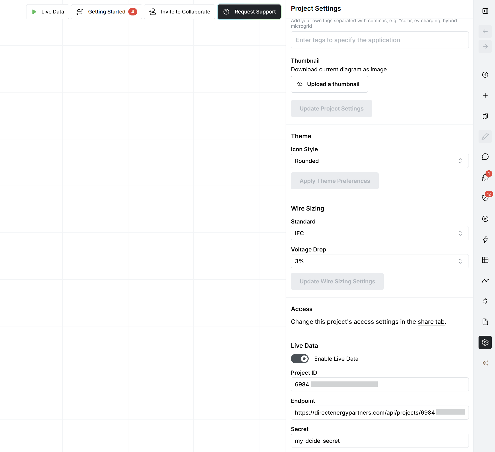
Open your project in DCIDE and navigate to the **Settings** tab.
Scroll down until you see the **Live Data** toggle button, and switch it on to enable live data for the project.
Once enabled, a **Project ID** will be shown in the settings. Copy this value, as it needs to be added to the
controller's `config.json` file.
Enter a **secret** to secure the live data stream between the controller and your DCIDE project. This prevents
other controllers or clients from being able to stream data into your project.
 ## Connect the Controller to DCIDE
With the Project ID and secret available, the controller needs to be configured to stream data to DCIDE.
Add a `dcide` entry to the controller's `config.json` file, and fill in the `projectId` and `secret` you copied
from your DCIDE project settings. For a full description of these parameters, see the
[Config File](/configure/configuration/config#dcide) documentation.
```json icon="code" theme={null}
{
"dcide": {
"projectId": "a1b2c3d4e5f6g7h8i9j0k1l2m3n4o5p6",
"secret": "my-dcide-secret"
}
}
```
The controller requires a stable internet connection in order to stream data to the DCIDE endpoint. Without
internet access, Live Data will not function, even if the configuration is correct.
Reboot the controller so that the updated `config.json` file is loaded and the controller starts streaming data
to your DCIDE project.
## Configure the DCIDE Diagram
Enabling Live Data and connecting the controller only makes the data stream available to your DCIDE project. To
display that data on the single line diagram, every component that the controller interfaces with must be linked to
its corresponding device by setting an **Identifier**.
On your DCIDE single line diagram, click the component you want to link to a device on the controller. This
opens the sidebar on the right.
In the sidebar, go to the **Edit** tab, then select **Live Data**, and scroll down to **Settings**.
In the **Identifier** field, enter the identifier for this component. This value must be identical to the `id` of
the corresponding device in the `devices.json` file on the controller.
Repeat this process for every component on the diagram that corresponds to a device on the controller. Any
component without a matching identifier will not display live data.
## Connect the Controller to DCIDE
With the Project ID and secret available, the controller needs to be configured to stream data to DCIDE.
Add a `dcide` entry to the controller's `config.json` file, and fill in the `projectId` and `secret` you copied
from your DCIDE project settings. For a full description of these parameters, see the
[Config File](/configure/configuration/config#dcide) documentation.
```json icon="code" theme={null}
{
"dcide": {
"projectId": "a1b2c3d4e5f6g7h8i9j0k1l2m3n4o5p6",
"secret": "my-dcide-secret"
}
}
```
The controller requires a stable internet connection in order to stream data to the DCIDE endpoint. Without
internet access, Live Data will not function, even if the configuration is correct.
Reboot the controller so that the updated `config.json` file is loaded and the controller starts streaming data
to your DCIDE project.
## Configure the DCIDE Diagram
Enabling Live Data and connecting the controller only makes the data stream available to your DCIDE project. To
display that data on the single line diagram, every component that the controller interfaces with must be linked to
its corresponding device by setting an **Identifier**.
On your DCIDE single line diagram, click the component you want to link to a device on the controller. This
opens the sidebar on the right.
In the sidebar, go to the **Edit** tab, then select **Live Data**, and scroll down to **Settings**.
In the **Identifier** field, enter the identifier for this component. This value must be identical to the `id` of
the corresponding device in the `devices.json` file on the controller.
Repeat this process for every component on the diagram that corresponds to a device on the controller. Any
component without a matching identifier will not display live data.
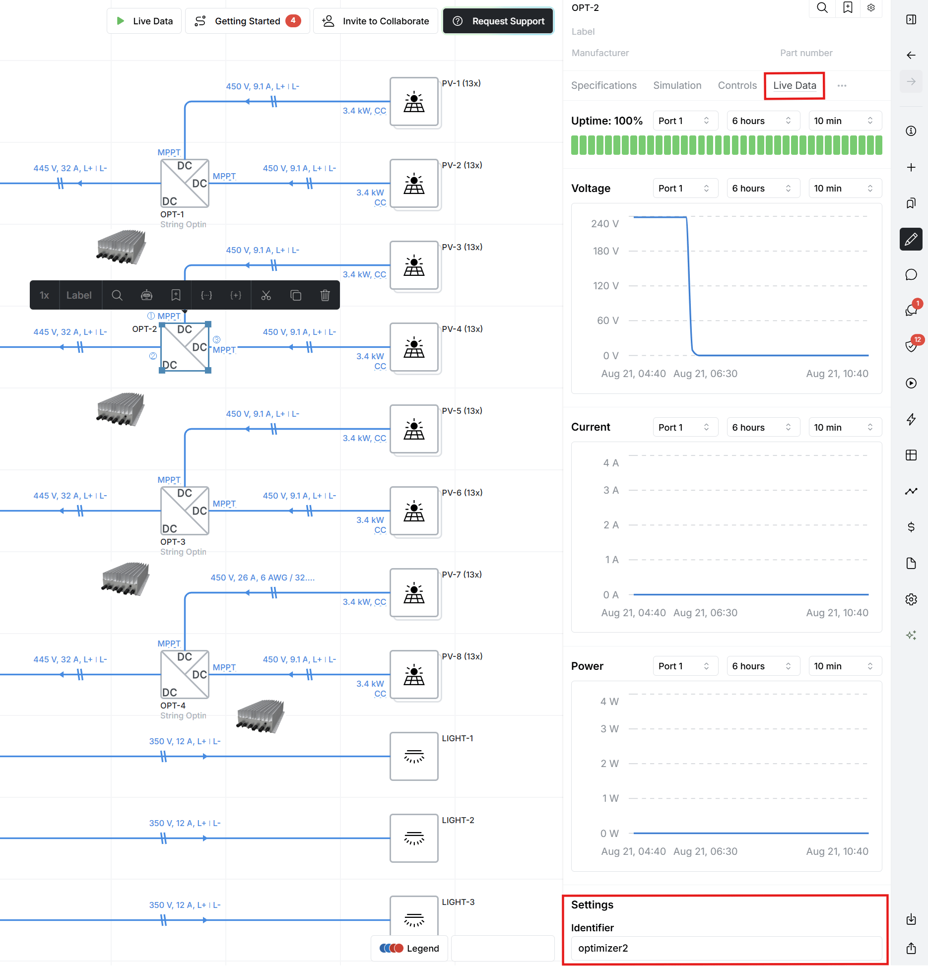 The identifier set on a DCIDE component must be identical to the `id` of the device as defined in `devices.json`.
If the values do not match, DCIDE will not be able to associate incoming data with that component. See the
[Devices File](/configure/devices/devices) documentation for more information on setting a device's `id`.
## Required Registers
DCIDE looks for specific register names in order to visualize data points and power flow on the diagram. For a
device to be visualized correctly, its address map must include the applicable registers below, read from the
corresponding connected device.
| Data Point | Register Name | Unit |
| ---------- | ------------------------------------ | ----------- |
| Voltage | `measure.ports.port{number}.voltage` | V (volt) |
| Current | `measure.ports.port{number}.current` | A (ampere) |
| Power | `measure.ports.port{number}.power` | W (watt) |
| SOC | `measure.ports.port1.soc` | % (percent) |
These registers must use **SI units**, as shown in the table above. Voltage must be reported in volts, current in
amperes, power in watts, and state of charge as a percentage. If a device reports values in different units (e.g.
millivolts or kilowatts), apply the appropriate `scaling` in the address map so the value is converted to SI units.
Otherwise, voltage, current, power flow, and SOC will not be displayed correctly on the DCIDE diagram.
For more information on defining registers and applying scaling in the address map, see the
[Address Map Files](/configure/address-map/index) documentation.
The identifier set on a DCIDE component must be identical to the `id` of the device as defined in `devices.json`.
If the values do not match, DCIDE will not be able to associate incoming data with that component. See the
[Devices File](/configure/devices/devices) documentation for more information on setting a device's `id`.
## Required Registers
DCIDE looks for specific register names in order to visualize data points and power flow on the diagram. For a
device to be visualized correctly, its address map must include the applicable registers below, read from the
corresponding connected device.
| Data Point | Register Name | Unit |
| ---------- | ------------------------------------ | ----------- |
| Voltage | `measure.ports.port{number}.voltage` | V (volt) |
| Current | `measure.ports.port{number}.current` | A (ampere) |
| Power | `measure.ports.port{number}.power` | W (watt) |
| SOC | `measure.ports.port1.soc` | % (percent) |
These registers must use **SI units**, as shown in the table above. Voltage must be reported in volts, current in
amperes, power in watts, and state of charge as a percentage. If a device reports values in different units (e.g.
millivolts or kilowatts), apply the appropriate `scaling` in the address map so the value is converted to SI units.
Otherwise, voltage, current, power flow, and SOC will not be displayed correctly on the DCIDE diagram.
For more information on defining registers and applying scaling in the address map, see the
[Address Map Files](/configure/address-map/index) documentation.